Features
Health and Safety
Sawmilling
Wood dust explosion suppression case studies
June 27, 2019 By Gilles Plourde
Explosive organic dusts (carbon based dusts such as wood, food, sugar, pharmaceutical, etc.) combust similarly to each other. While each may have its own characteristics, each will achieve its MAX pressure during the combustion process. The speed at which they reach this MAX pressure will differ between explosive dusts based on chemistry, particles sizes and moisture content.
Typical wood dust has a Kst of around 120bar*m/s and a Pmax of 8.2barg.
Typical sugar dust has a Kst of around 150bar*m/s and a Pmax of 8.5barg.
In a 200ft3 (5.66m3) vessel, the wood dust would reach its Pmax of 8.2barg in ~122ms. The sugar dust would reach its Pmax of 8.5barg in ~100ms. The average blink of eye is ~250ms. As we can see, both dusts would reach their MAX pressure within the blink of an eye.
Based on this, it’s safe to say that explosion protection does not differ from industry to industry based on which dust is being processed. What dictates explosion protection methods used from industry to industry is how the explosive dusts are processed/handled.
Food processing plants typically have smaller vessels used for batch processing. While they do have storage silos for their raw ingredients, the vessels in the process (mixers, dust collectors, cyclones, etc.) are typically much smaller than what we see in the wood industry. Some of the common vessels we see in the wood industry are large dust collectors and cyclones (volumes ~3000ft3), metering bins, and large dryers.
While the dust collectors and dryers tend to be large in volume, their general location (indoors, outdoors, proximity to walls, etc.), shape and design allow for similar explosion protection strategies to be applied as would be in smaller models. Explosion venting or suppression can be applied to the vessel to prevent the explosion originating within from rupturing the vessel and explosion isolation techniques can be applied to the interconnected lines, in order to prevent this explosion from propagating to interconnected equipment.
The cyclones and metering bins, however, present challenges when trying to prevent the explosion originating within from rupturing the vessel.
[This article is part of Dust Safety Week 2019. To read more articles on dust safety, click here.]
Explosion protection on cyclones
Cyclones by design typically have a short straight body with a tall hopper. Long straight bodies with short hoppers reduce the efficiency of the cyclone. Due to their design, installing explosion venting can be limited as, typically, the only location to install explosion vents is on top of the cyclone. This keeps the explosion vents out of the internal flow and has little effect on the efficiency of the cyclone.
One common issue is that most cyclones do not have much available space on top to install the explosion vents. While you do have some cases where the explosion vents are small enough to fit (typically when the cyclone is built to support high pressures 10psig or higher), in most cases, the amount of explosion venting needed to prevent the cyclone from rupturing from the explosion within exceeds the available space on top.
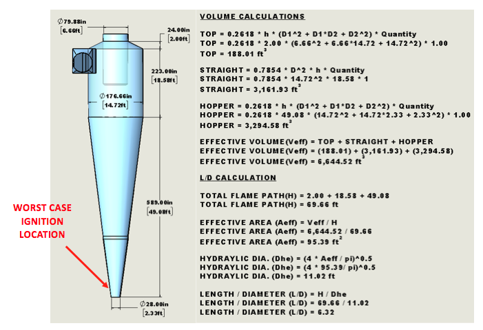
The following example shows the explosion vents required for a large cyclone:
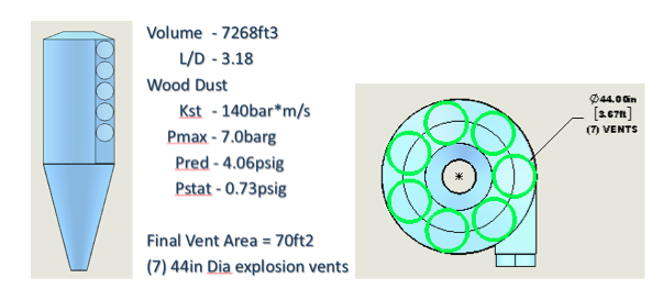
As we can see while all (7) explosion vents will fit on the top of the cyclone, you end up have explosion vents installed in the high flow area within the cyclone.
Another issue is that being tall and skinny shaped vessels, they will yield high L/D ratios (length to diameter). Per NFPA 68, the L/D ratio of any vessel is based on the worst-case scenario where the ignition of the explosion within the cyclone begins at the furthest point from the explosion vents. The following example highlights the L/D ratio of a typical cyclone, where the ignition would occur near the hopper discharge and the explosion vents installed on the top of the cyclone:
The L/D calculated is 6.32. L/D is directly related to the vent area calculated per NFPA 68. The higher the L/D, the more vent area is required, rendering it more difficult to fit the required explosion vents on the top of the cyclone.
NFPA 68 also has limitations on the MAX L/D ratio allowed for cyclones. Per current code, if the L/D calculated exceeds 6, explosion venting cannot be applied to the protected vessel. In our case above, L/D is 6.32, meaning even if we have the available space on top of the cyclone, explosion venting cannot be applied to this cyclone. The cyclone would need to be re-designed in order to reduce the L/D (shorter hopper, longer straight wall, etc.).
While these issues are very common for all sizes of cyclones, the larger cyclones seen in the wood industry tend to be more likely to fall prey to these problems. Either L/D is above 6, preventing explosion venting to be applied, or the L/D is too high and the explosion vent area calculated exceeds the available space on top of the cyclone where the explosion vents could be installed.
 For these reasons, explosion suppression techniques are more commonly used with large cyclones.
Explosion pressure detectors, installed on the top of the cyclone (out of the high flow areas), are used to detect the explosion originating within the cyclone.
Explosion suppression containers equipped with telescopic nozzles are installed on the hopper of the cyclone (away from the high flow area), which release a suppressant agent into the body of the cyclone when an explosion is detected. This agent absorbs the energy from the explosion and displaces oxygen, preventing the explosion from continuing to fully develop.
At the same moment, explosion isolation devices (suppressant containers or mechanical valves) installed on the interconnected lines (inlet, outlet and potentially hopper discharge) are activated, creating a chemical or mechanical barrier within the interconnected lines, preventing the explosion within the cyclone from propagating to interconnected equipment.
Explosion protection on metering bins
Metering bins by design typically have a lot of internal obstructions and limited space where explosion protection equipment such as explosion vents can be applied. They also have various fill levels by design. Due to this, installing explosion vents on the top of the metering bins would be the best approach in order to keep them away from product levels that could block the vent openings.
Installing explosion vents on the top of metering bins poses another issue that is related to the internal obstructions within the metering bins. Most metering bins have rollers and belt conveyors that can obstruct an explosion originating at the bottom of the metering bin from flowing freely to the explosion vents install on the top of the metering bin, causing higher reduced pressures (Pred) than would be expected in an unobstructed enclosure.
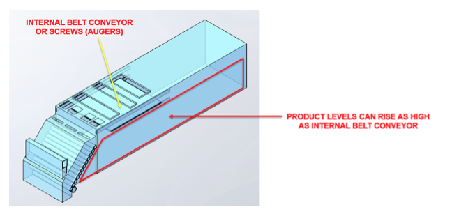
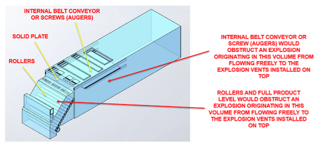
As we see in the two pictures above, there are several ignition locations where the internal obstructions of the metering bin would obstruct the explosion from flowing freely to the explosion vents, which would be installed on the top of the metering bin.
For these reasons, explosion suppression techniques are more commonly used with metering bins.
Explosion pressure detectors, installed at various locations on the metering bin, are used to detect the explosion originating within the metering bin.
Explosion suppression containers equipped with telescopic nozzles are installed at various locations on the metering bin, which release a suppressant agent into various sections of the metering bin when an explosion is detected. This agent absorbs the energy from the explosion and displaces oxygen, preventing the explosion from continuing to fully develop.
At the same moment, explosion isolation devices (suppressant containers or mechanical valves) installed on the interconnected lines (inlet, dust aspiration lines and product discharge) are activated, creating an chemical or mechanical barrier within the interconnected lines, preventing the explosion within the metering bin from propagating to interconnected equipment.
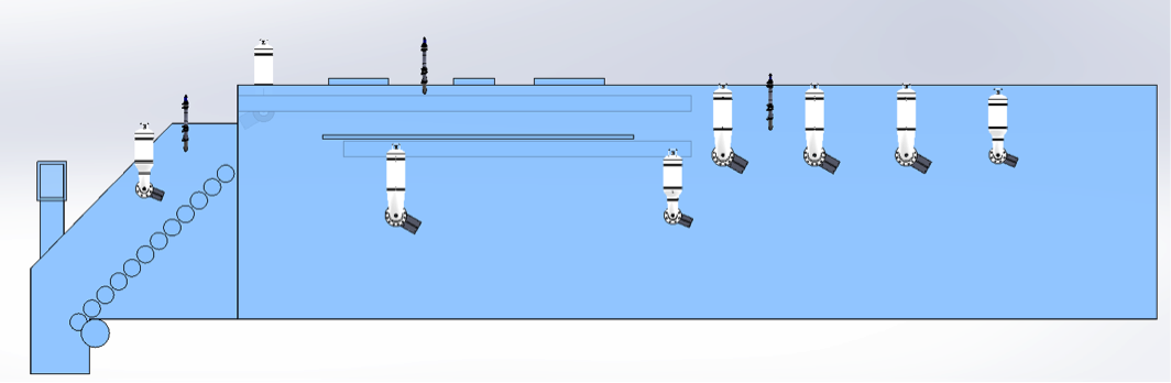
The locations of the pressure detectors and suppressant containers are such that an explosion is detected and suppressed regardless of fill levels and ignition location.
Conclusion
The priority in any explosion protection system is to prevent the vessel containing the explosion risk from rupturing, preventing secondary damage to surrounding equipment and personnel.
While there are several methods of explosion protection (explosion venting, explosion suppression, explosion containment), the most practical and economical method may not be the same for all vessels/applications.
Understanding the vessel operation and layout of the process provides the explosion protection application specialist the information needed to ensure the best explosion protection solution is being applied.
Gilles Plourde is the inside sales supervisor of explosion protection applications for Fike Canada, Inc. Gilles has years of experience designing and applying explosion protection solutions for companies both in Canadian and internationally. For more information go to www.fike.com or email FikeCanada@fike.com.
Print this page