New Gear
Equipment
Sawmilling
No Real Downtime
Many plants have been shut down temporarily due to the market conditions. Maintenance departments frequently take advantage of this time to repair or perform tests that can’t be done when the machines are operating. Many times the only attention a hydraulic system might get is an oil and filter change. Yet, there are several checks and procedures that can be done during down periods that will improve the efficiency and operation of the system when production demands are high. The following are preventive maintenance checks that will improve the performance of the systems and machines.
November 25, 2011 By Al Smiley Jr.
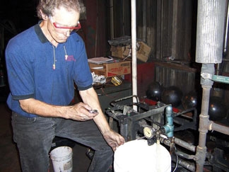 The author gets his hands Many plants have been shut down temporarily due to the market conditions. Maintenance departments frequently take advantage of this time to repair or perform t
Reservoir
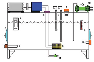
Now is an ideal time to clean the reservoir (Figure 1). Maintenance mechanics and electricians chuckle when I tell them that the reservoir should be cleaned at least once a year. While consulting with one large wood products plant, the mechanic said that the reservoir on one system hadn’t been cleaned since the mill started up 17 years ago! Other than oil storage, the two main purposes of the reservoir are to allow contaminants to settle and to dissipate heat. If the reservoir is not cleaned, it will act as a heat sink and can cause system temperatures to rise above 60°C. Oil will then start breaking down, causing sludge and varnish in the system.
Figure 1:
If the contaminants are not removed from the reservoir they will be drawn into the pump, causing premature failure of the system components. Be sure to use a lint-free cloth when cleaning out the reservoir.
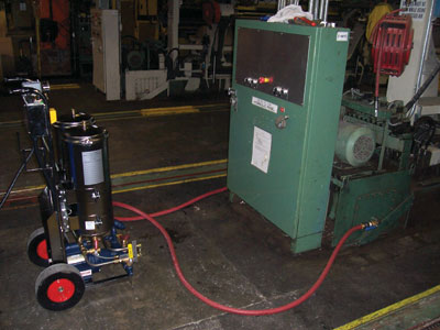
System cleaning and flushing: When the oil is removed from the reservoir, it should be filtered to 1 micron into a storage tank with a flushing and
filtering unit that will remove solid contaminants and water. Unless the oil is severely degraded, it is not necessary to change it. Run the oil through the 1 micron filters when re-filling the unit. The entire system should then be flushed to clean the oil in the lines to the valves and actuators. Figure 2 shows the flushing unit that is used by our consultants during this process.
Figure 2:
System flushing is done by connecting the inlet and outlet lines of the cylinders and motors together. If possible, electrically or manually actuate the directional valves to allow the fluid to re-circulate through the piping. If this is not possible, then bypass the directional valves by connecting the pressure and tank lines to the outlet lines to the actuators. Use the existing pump on the machine to re-circulate the oil through the lines. Connect the flushing unit so that it re-circulates the oil in the reservoir through the 1 micron filters. Allow the system to run for as long as possible. In Figure 3, the purity of the oil is shown for a system before it was flushed, then after 1, 4 and 16 hours.
Figure 3:

Reservoir heater setting: Check the heater thermostat (no. 2 in Figure 1) on the reservoir to verify that it will turn on at a minimum of 21°C. If the pump is mounted on top of the reservoir, and the oil temperature drops below approximately 16°C, cavitation will occur.
Oil level switches: Most reservoirs use two switch settings (no. 7 in Figure 1), a warning and a shutdown. The problem with this is that the difference between the two levels may be several hundred gallons of oil. By eliminating the warning switch and setting the shutdown at a higher level, oil loss will be minimal when a hose ruptures.
Breather cap: Verify that the breather cap (no. 8 in Figure 1) has a rating of approximately 10 microns. This is the first line of defence for contaminants entering the tank. Depending on the location, the breather cap may need to be changed a couple of times a year. Other options include pressurizing the reservoir with an internal bladder, or using a moisture removal type breather.
High Temp Switch
Oil will start breaking down at 60°C, and many systems will not shut the unit down until the oil temperature reaches 71°C. Hydraulic systems are designed to operate below 60°C. If the oil temperature rises above that level, there’s a problem somewhere in the system. This could be caused by a cooler malfunction, excessive bypassing at the pump, valves, cylinders, and hydraulic motors. Set the high temperature switch (no. 10 in Figure 1) at 60°C to shut the pump off, preventing oil breakdown.
Heat Exchanger
The tubes in a water type cooler (no. 12 in Figure 1) should be flushed periodically to remove deposits. A mild alkaline solution such as Oakite or a 1.5% solution of sodium hydroxide or nitric acid can be used. If an air cooler is used, verify that the cooler fan is turned on at approximately 49° to 50°C, and turned off at 49°. Combs should be used to straighten the fins on the unit if necessary.
Pump Testing
On variable volume pumps, check the flow out of the case drain line by porting the line into a container and timing it. This test should be made with the outlet pressure at maximum. It is not recommended that the line be held during this test. Secure the line to the container prior to starting the pump. The normal case flow is 1-5% of the maximum pump volume. Vane pumps usually bypass more than piston type pumps. If 10% of the maximum volume flows out of the case drain line, then the pump should be changed.
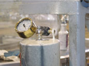
Fixed displacement pumps can be tested by checking the flow through the relief valve. Turn the pump on and record the flow out of the relief valve tank line for 1 minute (see photo on page 24). Then reduce the setting of the relief valve to its minimum setting. There should be less than a 10% difference in flow rates between the two tests. If a pump is badly worn, then the flow will be considerably less at the highest pressure.
Accumulator Testing
If piston accumulators are used, then the charging rig should be installed, and the oil bled off the top of the piston (Figure 4). With the pump on and the bleed valve open, there should be little or no flow exhausting out of the bleed valve. If a continuous flow exists, then the piston seals or barrel are badly worn. If no flow exists, then re-charge the accumulator to the proper dry nitrogen level.
Figure 4:
Bladder type accumulators should also be tested by installing the charging rig on the valve stem. Due to osmosis, the dry nitrogen can seep through the bladder over a long period of time. If necessary, pre-charge to the recommended pressure.
Hoses
Check the hoses in the system for the proper length and wear. Hoses infrequently burst because the rated working pressure is exceeded. They normally rupture because of a poor crimp or the hose is rubbing on a beam, another hose, etc. Hose sleeves are available on a reel from a variety of manufacturers if rubbing cannot be avoided.
Hoses should usually not exceed approximately four feet in length unless they move with a machine. Also inspect the system piping to verify that prior to connecting to a valve bank or cylinder, a hose is installed. The hose will absorb the hydraulic shock that is generated when the oil is rapidly deadheaded. An exception to this rule is that hard piping should always be used when connecting to a vertical or suspended type load. Pilot operated check valves and counterbalance valves are used to hold the load in the raised position.
Clamps
Inspect the system clamps to verify that that the proper hydraulic clamps are used to clamp hydraulic lines. Beam and conduit clamps are not acceptable, as they will not absorb the shock generated in the piping or tubing. The clamps should be spaced approximately five feet apart. A clamp should also be installed within 6″ of the pipe or tubing termination point.
Once the system is thoroughly inspected and upgraded, a preventive maintenance schedule should be developed to perform these checks on a regular basis. Many times no thought is given to the hydraulic system as long as it is running and the machine is operating. By performing the checks in this article, your systems will operate at maximum efficiency, operate safer and reduce downtime once the mill is back producing.
Hydraulics is a regular column written specifically for Canadian Wood Products. Al Smiley Jr. is the founder of GPM Hydraulic Consulting Inc., and has provided in-plant trouble-shooting, consulting, and training services to wood products companies in the US and Canada since 1987. He is registered with the Fluid Power Society as a Fluid Power Specialist. Send questions to: Hydraulics, 90 Morgan Rd., Unit 14, Baie d’Urfé, QC, H9X 3A8 or by fax to (514) 457-2558. For information about GPM Hydraulic Consulting, call (770) 464-0777.
Print this page