Features
Maintenance
Sawmilling
Troubleshooting hydraulics issues
December 2, 2015 - When troubleshooting hydraulics issues throughout a sawmill, it is imperative that each situation is approached with the best practices for proper repairs that will not just lead to a short-term fix, but a long-term solution.
December 9, 2015 By Al Smiley
 Having hydraulic schematics When troubleshooting hydraulics issues throughout a sawmill
This article looks at five common mistakes that get made when the proper skills, process and parts are not factored in during a repair.
Mistake No. 1 – Hydraulic pressures are improperly set
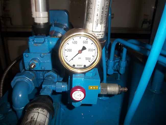
On every hydraulic system there are, usually, a multitude of adjustments to be made. When a machine problem occurs, knobs on the hydraulic pump and valves are adjusted to see if this solves the machine problem. Unfortunately, the person doing the adjusting usually has no idea what the effect is on the machine. Pressures in a hydraulic system are usually set too high. The thinking is the higher the pressure, the faster the machine will run. Consider the following real-case scenario that occurred at a wood products plant:
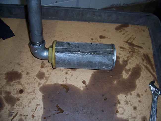
A company had severe shock and leakage problems on a piece of mobile equipment. The pump was also being changed at intervals of once per month. There was an adjustment on the pump (called a compensator), which limited the maximum system pressure. There was also a relief valve in the system that was used as an extreme safety device and a shock absorber. The recommended settings of the compensator and relief valve were 1,500 PSI and 1,750 PSI, respectively. When the stacker started and stopped, the pressure gauge needle spiked to maximum (3,000 PSI), vibrated, then settled in at 1,800 PSI. This indicated that the compensator and relief valve were both set too high. After resetting the compensator and relief valves to the recommended settings the pressure went up momentarily to 1,750 PSI (relief setting) then settled in at 1,500 PSI (compensator setting). Consider the difference in the force exerted on the 10” boom cylinder (78.54 sq. inches of area) with the relief valve at 3,000 PSI and at 1,750 PSI:
- Force with relief at 3,000 PSI = PSI X Area
- Force with relief at 3,000 PSI = 3,000 X 78.54 sq. inches of area
- Force with relief at 3,000 PSI = 235,620 lbs. of force
- Force with relief at 1,750 PSI = PSI X Area
- Force with relief at 1,750 PSI = 1,750 X 78.54 sq. inches of area
- Force with relief at 1,750 PSI = 137,445 lbs. of force
The difference in force? 98,175 lbs.! Once the pressures were properly set the shock was eliminated and the life of the pump was increased. After the clamps and O-rings were replaced the leakage stopped as well.
Mistake No. 2 – Lack of accumulator and hydraulic safety procedures
When a machine is worked on, the pump electric drive motor is turned off and the lock out and tag out procedures are done. The pressure gauge is rarely checked before working on or around the machine. Accumulators store hydraulic energy in the form of pressurized fluid. Most systems contain an automatic or manual dump valve that will allow the high-pressure fluid in the accumulator to dump to the tank permitting the pressure to drop to 0 PSI. The automatic dump valves can fail closed, which will maintain the pressurized oil in the accumulator. If a line is taken off or a component removed, then the individual can become injected with high-pressure fluid. When a manual dump valve is used, the human factor enters the equation. At one plant, a young millwright was severely injured when he was struck with high-pressure oil when he failed to open the hand valve. There was no procedure in place for opening the valve before working on the system.
Many times the gauge is located on the pump side of the check valve and not the accumulator side. When the pump is turned off, the gauge will drop to zero as the oil bleeds to tank through the internal tolerances of the hydraulic pump. Therefore, the maintenance person or operator thinks that the pressure is at zero and has no way of knowing if the pressurized fluid in the accumulator has been released or not. On systems of this design, a gauge needs to be installed at, or near, the accumulator.
Mistake No. 3 – Poor troubleshooting techniques
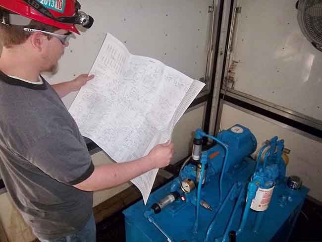
In our maintenance hydraulic troubleshooting workshops, we stress that the quickest and easiest method of troubleshooting the machine is to use the hydraulic schematic. The response from the students is usually one of the following:
- Management won’t give us time to troubleshoot.
- We don’t have the schematics or know where they are.
- We don’t know how to read the schematics.
When a hydraulic problem occurs, information must be gathered in order to make a decision as to what component is causing the problem. A few examples are checking the pump case drain flow, checking the feedback from a proportional valve LVDT, and checking for heat in the system. Many times the supervisor intervenes and demands that the pump, cylinder or other component be changed. At one plant, a supervisor instructed a millwright not to troubleshoot, but to manually actuate a directional valve. This resulted in an accumulator discharging into a partially filled 5,000-gallon reservoir. The top of the reservoir blew off, which shut the mill down for seven days.
Hydraulic schematics are usually located inside the machine manufacturer’s manual, which is kept in a maintenance office or storeroom. When a hydraulic problem occurs, the last thing that the maintenance person is going to do is to take 15 or 20 minutes to find the print. After all, when the machine is down, time is money. A better option is to mount the larger prints out by the system under a Plexiglas cover. Smaller prints can be laminated and similarly located. If the schematic is readily available, it will be used.
The most common statement I hear from the mechanic and electrician when consulting with the plant on a problem is, “I don’t know much about hydraulics.” This means that they have either not been trained properly or have forgotten what they have learned. On the other hand, I go to plants where we have conducted machinery-specific hydraulic training and I hear “We use your manuals and schematics all the time.” Without the proper training you cannot expect your maintenance crew to troubleshoot effectively.
Having hydraulic schematics
Mistake No. 4 – Poor hydraulic reservoir and oil maintenance
While most plants do a good job at maintaining the system filters, the reservoir is usually not given any attention. When a system is designed, the size of the reservoir is factored into the amount of heat that will be removed from the system. Reservoirs should be cleaned a minimum of once a year to allow some of the heat in the oil to be released into the atmosphere. On a log loader in Ontario, the reservoir had not been drained and cleaned in 17 years. A thick layer of sludge was found on the bottom of the tank once the oil was drained out. The suction strainer split, which allowed contaminants to enter the pump. A reservoir that is not cleaned can act as an incubator instead of dissipating the heat in the oil.
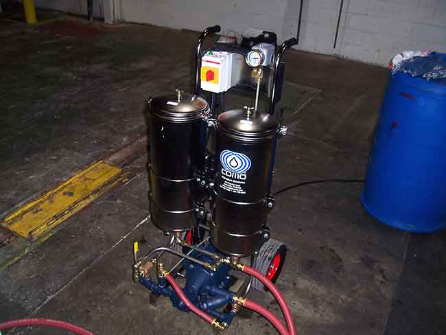
Another common problem is that oil is frequently added to the system that is not filtered. This should never be done! Oil that leaves the refinery is clean; however, by the time it is stored in transfer trucks and drums it might meet a 50-micron standard when added to the tank. Many systems have connections for attaching the fill pump hose so that the oil in the drum is ported through the system filter before it enters the reservoir. A standalone filter cart can also be used when refilling the tank. The unit shown on page 38 not only removes contaminants to one micron but also removes up to two gallons of water.
Mistake No. 5 – Components are replaced that don’t have the same part numbers
When a hydraulic problem occurs, there is usually one component that has failed. It is essential to match the part numbers between the new and old components. Hydraulic pumps and valves that look alike are not necessarily the same. Each number or letter in the part number indicates a feature about the pump or valve. If there is one letter or number difference, then the manufacturer’s literature should be consulted as to what the difference is. A few years ago, a plant had the main directional valve fail on their crane grapple. The valve had the following part number: DG5S8-2A-T-50.
A local vendor was called and said they had a valve that had the same spool configuration and the same mounting pattern in their central distribution centre. The valve with the following part number was flown in and delivered to the plant the next day: DG5S8-2A-E-T-50.
When the valve was installed, the grapple cylinders still would not extend and retract. The manufacturer of the valve was then called and given the two different numbers. The original valve was an internally hydraulically piloted (letter “E” omitted) and drained valve. The valve sent by the vendor was an externally piloted and internally drained valve. Since there was no external pilot line connected in the system the new valve would not work. To solve the problem, the valve manufacturer told the mechanic at the plant to remove the internal Allen head plug in the “P” port and to install it in the “X” port. Once this was done the grapple operated normally, but only after 18 hours of downtime!
These common mistakes are mostly made because of lack of knowledge. When the machine is down, the supervisor, mechanic and electrician are going to do whatever is necessary to get the machine back on line in the shortest period of time. By making sure that these top-five errors don’t occur at your plant, the down time will be reduced, your plant will operate safer and hydraulic troubleshooting will improve.
Print this page